
The following information is provided to assist supply only customers determine the manufacturing sizes and details of their bifolding door.
If you intend to choose our supply and fit service our installer will carry out a survey to obtain all the details we will need or for new apertures not yet built we can agree the aperture size with you.
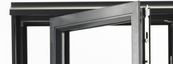
Aluminium Bifold Doors
Measuring
You can download our survey form which will help guide you in calculating the size and configuration for your folding sliding door.
-
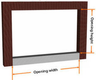
1. Measuring The Aperture
The width and height of your bifold door is the structural opening size less a fitting tolerance.
We recommend a 10 - 15mm fitting tolerance is allowed between manufacturing sizes and the smallest width and height dimension(see below).
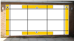
Use a large spirit level and measure the cross corners of the aperture to ensure the opening is square and true.
Take three width and three height measurements and deduct 10mm from the smallest to determine the actual manufacturing sizes of your door.
-
2. Track Requirement
Now you need to decide on the best threshold and track option for your door.
The weathered threshold shown is recommended for external doors and can be supplied with an optional projecting cill.
-
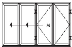
3. Door Style
Finally we will need to know which folding door style you require (viewed from the outside) and whether you require the door to fold and slide outwards or inwards. For example this door has 3 panels moving left and one hinged right.
This provides a French door type design for the end two panels with the panel marked M being the Main traffic door.
-
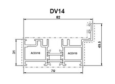
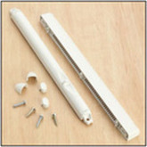
4. Trickle Ventilators
Trickle vents are usually required for external doors and these are concealed in an exclusive 42mm frame extender fitted at the top of the door eliminating the need for face fixed trickle vents that spoil the look of most bifold doors.
-
5. Accessories
Handle choice: gold, white, chrome and black.
Installation Guide
An installation guide is provided with all bifold doors.
Timber Bifold Doors
Timber folding sliding doors require a structural opening constructed from timber, steel, brick, concrete or concrete block to ensure a firm structural fixing. Thermalite, cinder or breeze blocks are not suitable.
The head of the opening must be constructed from steel, structural timber or concrete. Light metal lintels or timber sub frames will not provide a firm structural fixing.
Measuring
You can download our survey form which will help guide you in calculating the size and configuration for your folding sliding door.
-
1. Measuring The Aperture
The width and height of your bifold door is the structural opening size less a fitting tolerance.
We recommend a 10 - 15mm fitting tolerance is allowed between manufacturing sizes and the smallest width and height dimension(see below).
Use a large spirit level and measure the cross corners of the aperture to ensure the opening is square and true.
Take three width and three height measurements and deduct 10mm from the smallest to determine the actual manufacturing sizes of your door.


-
2. Track Requirement
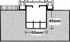
Now you need to decide on the best threshold and track option for your door.
Note that if you are selecting the flush track option the height dimension is to the underside of the sunken track i.e. 45mm below your finished floor level.
-
3. Door Style
Finally we will need to know which folding door style you require (viewed from the outside) and whether you require the door to fold and slide outwards or inwards. For example this door has 3 panels moving left and one hinged right.
This provides a French door type design for the end two panels with the panel marked M being the Main traffic door.

-
4. Trickle Ventilators
Most external bifolding doors require trickle ventilators to comply with Building Regulation requirements and where required they will be fitted to a 50mm high frame extender that is fitted to the top of the frame head.
When doors are being installed in a kitchen area using a gas oven gas vents should be specified to ensure permanent trickle ventilation is provided.
-
5. Accessories
Handle choice: gold, white, chrome and black.
Doors are assembled during the installation process which makes fitting one of our timber folding doors fast and easy. As you work through the fitting process you will fit the bottom track, the two side jambs and the top track and then proceed to install the individual panels that make up your new folding sliding door. The bifolding door panels should be bench glazed prior to installation which will ensure a positive seal for the glass against the external glazing gasket.
An installation and operating guide is provided with your door but you can also download a copy here.
Alternatively, there are are a series of short instruction videos below that will take you through each part of the fitting process in sequence.
1. Fitting Bottom Track
It is essential that the bottom track is fitted flat and level in both directions. Fixing holes should be pre-drilled 100mm from each end and at 500mm centres. The track port is positioned at the stacking side.
2. Fitting First Side Frame
The first jamb to fit is the one that the door will stack open against. Ensure the jamb is fixed square and level on both faces and must be firmly fixed to the wall to carry the weight of the doors. Thermalite, breeze block or cavity fixed jamb must be firmly strapped to ensure no side to side or rocking movement.
3. Positioning The Top Track
Position the top track on top of the jamb and place the other jamb in position under the top track to hold it in place. If it is practically possible do not fix the top track at this stage.
4. Fitting Second Side Frame
The second jamb is fixed square on the track and level on both faces. This jamb must be firmly fixed to carry the weight of the doors as first side frame.
5. Fitting The Top Track
The top track can now be fixed into position. It must be firm and level in both directions to ensure smooth operation of the door. Fix at the same centres as the bottom track.
6. Fitting Hinges And Rollers
Remove the top and bottom hinges from the connecting edge of the 2nd and 3rd (and 4th & 5th if applicable) panel and attach them to the rollers. Set the rollers by winding the bottom Allen bolt to 32mm for the bottom roller and 35mm for the top. The measurement is taken from the top of the black carrier to the underside of the T on the roller
7. Installing Rollers
Insert all the rollers into the track ensuring that the hinges are positioned on the correct sides.
8. Installing First Panel
Lift the first panel into position. We recommend that two persons lift the panels. For easy positioning, place timber on the floor so that the top of the timber is 8mm higher than the top of the bottom track. Lift the panel onto to timber. Locate the hinges and fix to the first jamb. Check the panel for parallel positioning and clearance with the tracks.
9. Installing Half Cylinder To Intermediate Panels
Insert the half cylinder with the keys in. Rotate the keys to position the cylinder accurately into the lock. Insert the fixing bolt through the hole in the lock face plate and tighten. Be careful not to over tighten the fixing bolt. Mark, pre-drill and screw on the cylinder cover. Half cylinders are not supplied as standard.
11. Fixing Intermediate Handles
Using the same method as the first panel, fix the second panel. Slide the top and bottom roller onto the panel, position and fix. Check the panel for parallel positioning and clearance with the tracks. Adjustment to the rollers may be required at this stage. Note: For 4,5 and 6 panel door sets, repeat steps above. For 2, 4, or 6 panels folding in one direction, a solid hinge is attached to the top and bottom roller of the last panel.
12. Fit The Traffic Door
Fit the traffic or swing door by initially attaching with one screw per hinge before fitting remainder of hinges.
13. Fit The Full Cylinder To The Traffic Door
Insert the full cylinder with the keys in. Rotate the keys to position the cylinder accurately into the lock. Insert the fixing bolt through the hole in the lock face plate and tighten. Be careful not to over tighten the fixing bolt. Mark, pre-drill and screw on the cylinder covers.
14. Fix The Handle To The Traffic Door
Insert the longer square spindle into the lock. The spindle should project no more than 5mm from the face of the panel. Mark, pre-drill and screw on the handle with the lever facing horizontally.
15. Fitting The Lock Keeps
Open the door and lock the traffic door into the track. Slide the door closed so that it is positioned 50mm from the closing jamb. Place masking tape on the frame and mark the position of the bolts. Mark, pre-drill and screw on the keeps in accordance to your bolt markings.
16. Finishing Off
Cut to size and pin the fixing covers into the jambs. Seal the perimeter of the door frame.
17. Glazing Including Toe And Heeling
The glazing process including toe and heeling the sealed units to ensure correct operation of the door.
18. Roller Adjustment
How to adjust the vertical heights of the panels.
19. Fitting A Panel Clip
20. Resetting A Shoot Bolt
This video shows how to reset a shoot bolt if it has become detached from the main lock.
uPVC Bifold Doors
Our upvc folding doors are suitable for installation into structural openings constructed from timber, brick, concrete or concrete block to ensure correct operation of the door. The frame head should be fixed to steel, structural timber or a concrete lintel to ensure a firm structural fixing.
Measuring
You can download our survey form which will help guide you in calculating the size and configuration for your folding sliding door.
-
1. Measuring The Aperture
The width and height of your bifold door is the structural opening size less a fitting tolerance.
We recommend a 10mm fitting tolerance is allowed between manufacturing sizes and the smallest width and height dimension(see below).
Use a large spirit level and measure the cross corners of the aperture to ensure the opening is square and true.
Take three width and three height measurements and deduct 10mm from the smallest to determine the actual manufacturing sizes of your door.


-
2. Track Requirement
Now you need to decide on the best threshold and track option for your door.
Note that if you are selecting the flush track option the height dimension is to the underside of the sunken track i.e. 45mm below your finished floor level.

-
3. Door Style
Finally we will need to know which folding door style you require (viewed from the outside) and whether you require the door to fold and slide outwards or inwards. For example this door has 3 panels moving left and one hinged right.
This provides a French door type design for the end two panels with the panel marked M being the Main traffic door.

-
4. Trickle Ventilators
Most external bifolding doors require trickle ventilators to comply with Building Regulation requirements and where required they will be fitted to a 50mm high frame extender that is fitted to the top of the frame head.
When doors are being installed in a kitchen area using a gas oven gas vents should be specified to ensure permanent trickle ventilation is provided.

-
5. Accessories
Handle choice: gold, white, chrome and black.
Installation Guide
All our Timberlook PVCu bifold doors are supplied with a comprehensive installation guide.